Conversion of analog DJ mixer to USB MIDI connection
I had an old Stanton RM-3S analog mixer in my basement unused for few years, so I decide to do something with it. Because times have changed, I already use a setup with two turntables (an old Vestax PDX2000) and a MIDI mixer so I decided to modify it to the actual needs - convert it to a USB MIDI mixer, usable with DJ software like TRAKTOR..
Functionality & MIDI mapping
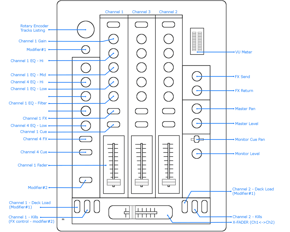
Original idea was to keep all control items and functions exactly the same as it's on original mixer, just convert it to MIDI. Because there are several items that are useless in the new USB MIDI concept (e.g. microphone inputs) I decide to replace them by few usefull things in order to achieve full control over DJ software (TRAKTOR in my case) like listing through track list in library.
Big microphone input (XLR connector) was replaced by rotary encoder with appropriate knob for track listing in the DJ software. Also opening below (jack input) was used for additional button for modifier (shift function) in MIDI mapping for TRAKTOR SCRATCH PRO 2.
MIDI Mapping:
Functionality:
Hardware
Remove old:
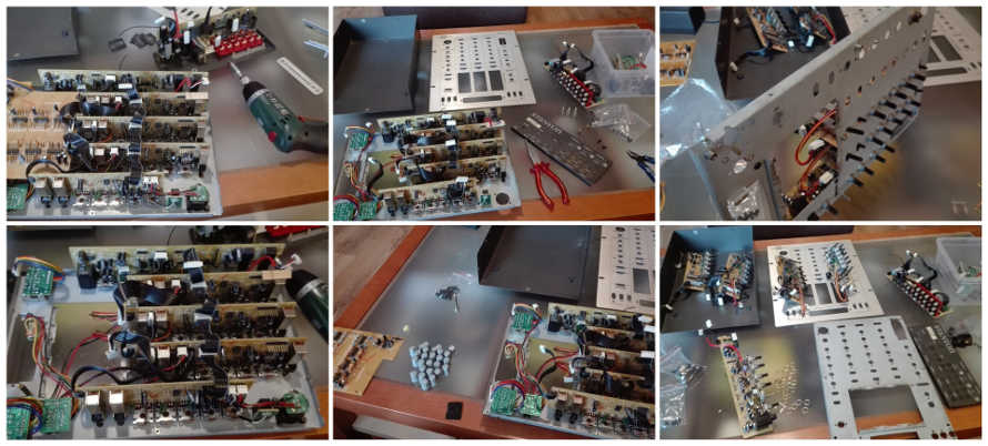
I decide to completely remove old PCBs and create my own with adequate dimensions and layout in order to fit to the original case and the top panel. First step was removing of all old parts, disconnection of all printed circuit boards and disassembly of the mixer to individual parts:
Create new:
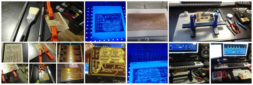
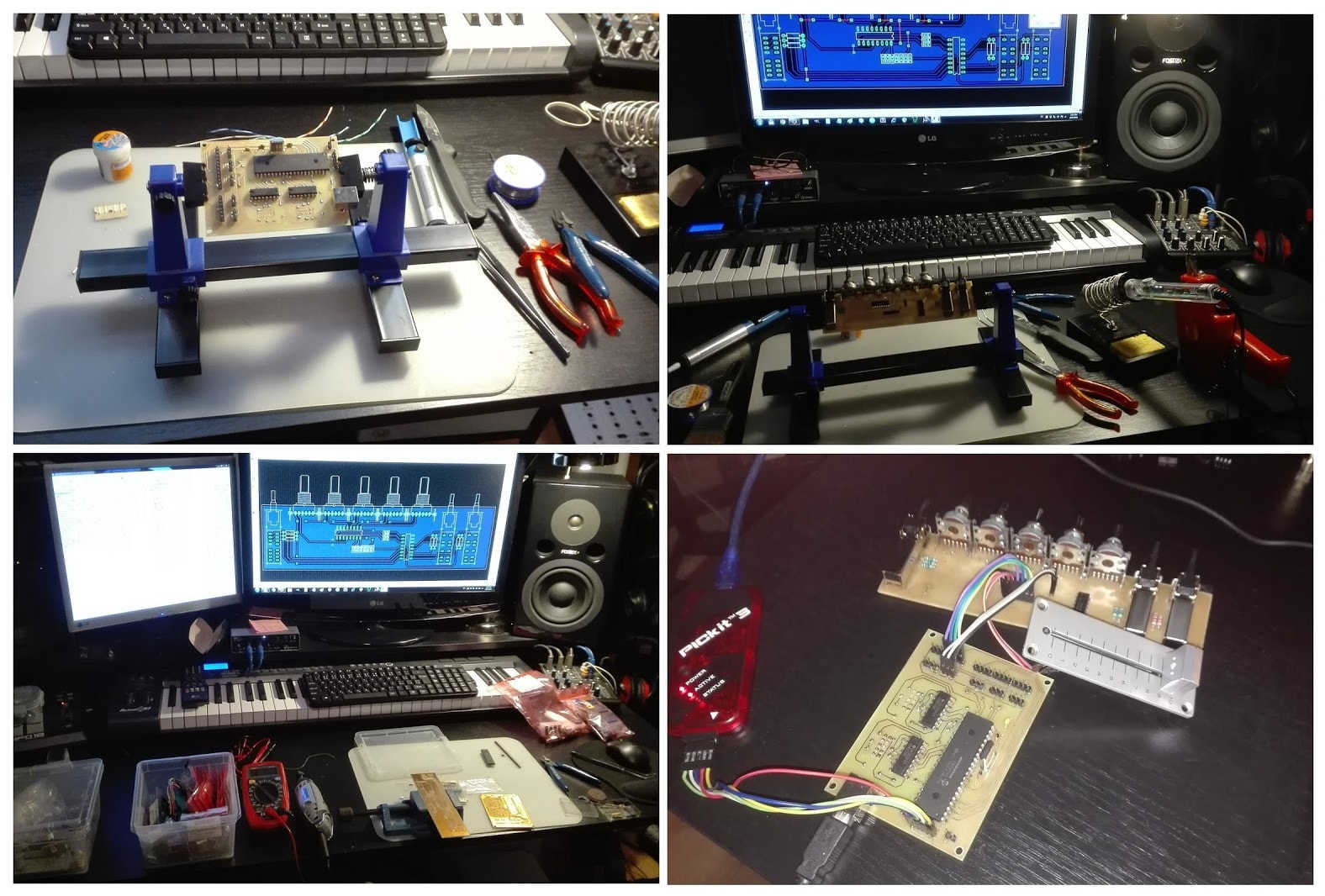
Next step was measurement of original layout of all items on the top panel (potentiometers, switches..) and to design new versions of original PCBs (Printed Circuit Boards) and also few completely new ones for the additional rotary encoder and shift button. Subsequently production. I've designed (Eagle 7.2.0) and created new PCB by photo method at home. There are several boards for particular channels and one main board with micro-controller (PIC18F4550) for processing of signals from the boards and sending the USB-MIDI data to the computer. First one was the main-board, than board for the one channel and simple firmware programming in order to test it in minimal configuration.
Wiring and cables:
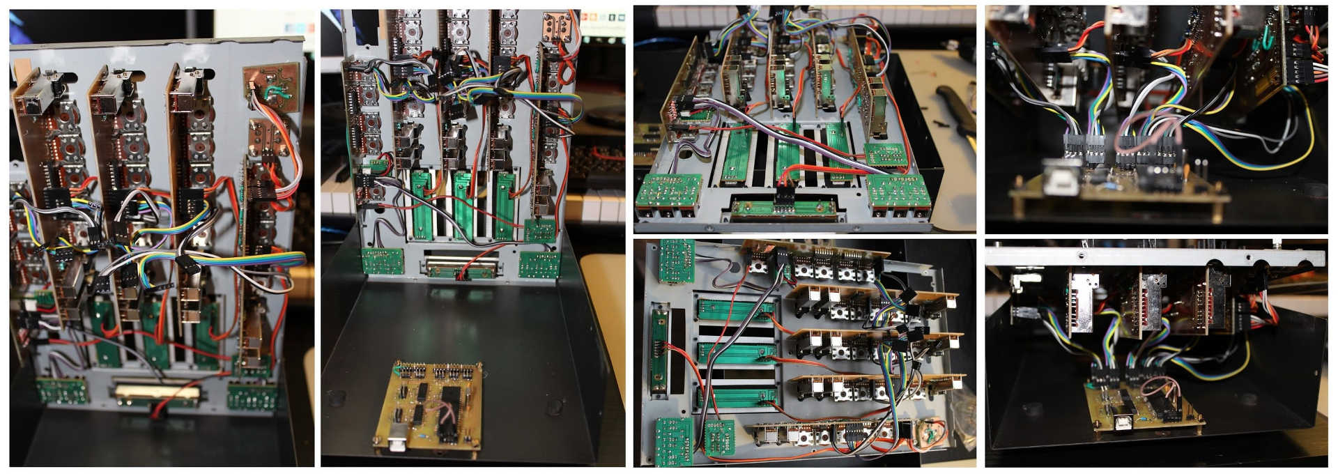
After successful test of main board with connected first channel board was the production of remaining PCBs of all channels (2, 3, 4), LED VU Meter, Rotary knob and modifier (shift) button. After that connection of all wires and cabling.
Front panel:
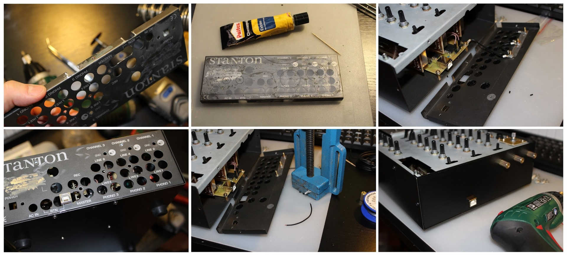
Modification of the front panel was simple. I cut out square opening on the place of USB connector to original panel by mini saw DREMEL tool. Next I cut out square shape from solid plastic sheet to the same dimensions like original panel and stuck it to the panel. After that I painted the stuck plastic cover by spray. At the end I just cut out the opening for USB with scalpel. Only one thing that I left on the front panel are connection points for the grounding and connect them to main-board GND part.
Knobs:
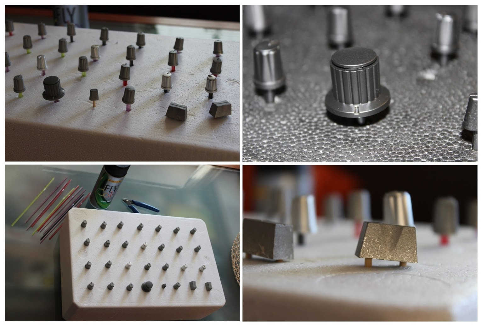
Original knobs was quite worn out and big knob for rotary encoder was gray color - necessary to repaint all knobs..
Firmware
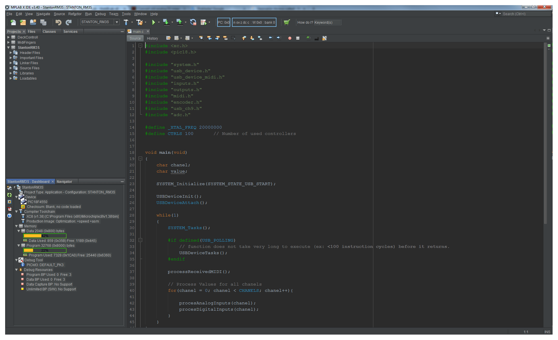
As mentioned above "the brain" responsible for signals processing and sending MIDI data via USB to the computer is PIC micro-controller 18F4550 by Microchip corporation. For firmware development I use MPLAB X IDE 3.40. and basic C compiler for 8bit micro-controllers family XC8. For debugging and programming the PIC chip was used PICKIT3 programmer. USB MIDI interface is established by Microchip Libraries for Applications for USB MIDI communications. Related files were pulled out from the libraries and included to the project in order to achieve project portability in the scope of one folder without the need of MLA installed. Download of the MPLAB project is available in download section below.
Downloads
![]() Eagle CAD File (schematic + PCB)
Eagle CAD File (schematic + PCB)
