Arcade Buttons MIDI Controller
A few years ago I found MIDI Fighter. MIDI controller with arcade buttons instead of traditional pads. Great idea. In the beginning, it was a DIY solution and that was also my inspiration. Arcade buttons are perfect for finger drumming or, in my case, for Cue Points control (with multi-coloured LEDs it's a perfect solution) in any DJ software (like NI TRAKTOR or Mixxx). Great idea of how to extend my DJ setup.
Functionality
4x4 matrix Arcade buttons keypad:

The matrix of 4x4 arcade buttons has a pretty simple function. Sending Note On message when a button is pressed and Note Off message when the button is released. The number of the note key depends on the button and also on the bank selection. For the Note key, MIDI protocol allows 128 values (0-127) what is given by 7 bits of the 2nd DATA byte of MIDI protocol, 1st bit determines if the Byte is Status or Data type. With 16 buttons it's 8 bank possibility (16 * 8). Along with the note key MIDI message contains also information about the channel (there is 16 MIDI channel according to the specification). MIDI channel is determined by 4 bits of 1s Byte.
Here is an extract from the MIDI specification from midi.org website.
| Status D7----D0 |
Data Byte(s) D7----D0 |
Description |
Channel Voice Messages [nnnn = 0-15 (MIDI Channel Number 1-16)] |
||
| 1000nnnn | 0kkkkkkk 0vvvvvvv |
Note Off event. This message is sent when a note is released (ended). (kkkkkkk) is the key (note) number. (vvvvvvv) is the velocity. |
| 1001nnnn | 0kkkkkkk 0vvvvvvv |
Note On event. This message is sent when a note is depressed (start). (kkkkkkk) is the key (note) number. (vvvvvvv) is the velocity. |
4 tactile buttons for settings:

B1 - Bank change
B2 - Channel change
B3 - Reserve (at this moment, firmware v 1.0.1)
B4 - Select Color (of a pressed button)
Design
For PCBs design of the mainboard and the system buttons board were used Eagle CAD v.9. The overall design is made in Sketchup with "eagleup" plugin for exporting and importing eagle boards to the Sketchup.

Hardware
Main-Board
For logic and processing of all signals and MIDI data& communication with the computer is responsible 8-bit mid-range family micro-controller PIC18F4550 with USB connection ability. Main-board consists of the micro-controller and two 8-bit static shift registers (4021) for the processing of the buttons signals, the LEDs (SK9822 in serial connection) and holders (modified plug springs for PCb installation) for arcade buttons.

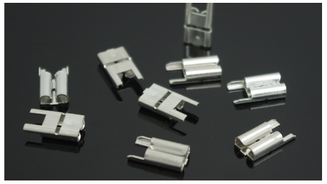
Plug spring for installation to PCB (has to be cut out one leg for better fit into the mainboard PCB)
All schematics are available in the download section.
System Buttons Board
is very simple. Just 4 tactile buttons with pullup resistors and connector.

Connection with mainboard is established by standard 6-wire ribbon cable through 6-pin IDC connectors.

Arcade Buttons
Used buttons are OEM 30mm transparent push buttons as a replacement for Arcade Sanwa buttons.
RGB LEDs - SK9822
Used backlit for buttons are SK9822 LEDs. I didn't use any specific library, the protocol is quite simple, so I just made a few functions to send the data to the LEDs outputs.


Plastic Body
The case is made of extruded PVC by cutting individual parts on X-CARVE CNC machine. The machine has GRBL controller so it receives a standard G-Code. The cutting tool is 2 flutes Upcut bit. As spindle is used Makita RC0700 router. RMP option has been set on the 3rd level (app. 12000 RPM).
The parts were glued up together and sanded to align the edges.

Then painted by common spray cans - lightly sanded between layers with 1000 grit sandpaper - 2 layers of base coat and 2 of the finish coat.

Firmware
The basis of the controller for signals processing and sending MIDI data via USB to the computer is PIC micro-controller 18F4550 by Microchip corporation. For firmware development, I use MPLAB X IDE (v5.05 at the time) and a basic C compiler for 8bit micro-controllers family XC8. For debugging and programming the PIC chip was used PICKIT3 programmer. USB MIDI interface is established by Microchip Libraries for Applications for USB MIDI communications. Related files were pulled out from the libraries and included to the project in order to achieve project portability in the scope of one folder so there is no need to have MLA installed. The download of the MPLAB project is available in the download section below.